Well my robot finally died. A couple of years ago I joined OculusVR and moved to Southern California. For two months I worked remotely from Austin and used the robot during that period, but after moving to Cali and being once again physically present in an office, I partially disassembled the robot and used it simply as a decoration. I recently was relocated to the Bay Area and during the move the robot was mishandled and broke. Not beyond repair mind you, but it's not worth fixing at this point. So this project and blog are officially over.
Today, telepresence robots are coming down dramatically in price (~2500) and are within reach of a remote IT worker, and I would suggest to anyone seriously interested in one for work purposes that they purchase one of these consumer products. It would be a lot more reliable and less fuss. But I learned a lot building this one and I'm glad that I had that experience. Oh, and I eventually met Johnny Lee in person and was able to thank him for the inspiration to undertake this project.
Tuesday, April 7, 2015
Sunday, June 10, 2012
Upcoming robot changes
I feel really bad that I have neglected this blog so much. Months ago I had intended to integrate a pair of VR glasses (head mounted displays) and a head tracking device to control the robot. The robot head would have acted as an extension of your physical body allowing you to look around the room as if you were really there. But along the way I got drawn into a number of other VR projects instead.
Free motion VR game tracking
Virtual Desktop
I have managed to do some maintenance and experimentation with the robot - mostly in the form of wireless networking. My office layout is such that it is almost exclusively walled offices instead of cubicles so it is impossible for me to rove from end to end on a single router. I tried many different configurations of routers and antennas both in the office and on the robot and have never found a workable solution. Instead I just put several access points and remotely signal the robot to switch access points when I move from area to area. Annoying? Yes, but it's the only way I can maintain a good connection throughout the office.
Also, I still have a lot of problems with the robot "browning" out and the computer dying during the docking sequence. I finally decided just to redesign the head and put the battery back in the computer. I don't want the additional weight but its the only way I can stop the robot from losing power. I'm working on that change in the next two weeks and will report on it.
Tuesday, October 11, 2011
DIY Telepresence Robot - Part 9
Upgraded Power Management
So after several months of operation I encountered a number of problems with the design. I would frequently (twice a day) lose control of the original robot and have to reboot the system because of connection problems in the USB/Serial interface between the laptop and iRobot Create. Additionally I had semi-frequent problems (twice a week) maintaining proper control of the PowerPod. It would occasionally go crazy, escape my control, and orient itself at odd angles. Those problems were annoying but relatively manageable for a while. However, when the battery charger in my original iRobot Create broke and I had to replace the iRobot, I began to have even worse issues. In addition to the original control loss problems, the iRobot Create would frequently "brown-out" while docking which would drop power to the laptop and leave it dead in the water. I would have to get a coworker to help me power up the system each time. These problems almost always occurred during the docking maneuver which itself draws a large amount of power, so without much evidence to go on I hypothesized that it was a power management issue.
I originally wired the laptop to theoretically draw up to 3A of power from the Create, but honestly I never really did any boundary testing to determine whether the hardware could handle this type of draw. Maybe the Create power pins cannot actually supply the 3A (maybe only 1 pin can draw fully at a time) or there is an undocumented total power limit that the battery can supply to the hardware. When this power ceiling is exceeded the Create crashes and power cycles. Another possibility is that the power state transition between not-charging and charging is sometimes not very smooth and causes a momentary drop in power. Either way it seemed like the best thing to do would be to minimize power draw as much as possible. I only had circumstantial evidence, but with nothing else to go on I went ahead and made changes in both hardware and software to reduce and smooth power usage.
First, I wanted to take all of my USB components off the laptop motherboard power supply. The video camera and PowerPod in particular both draw a fair amount of power and it might be difficult for this low power netbook to power them adequately while also running itself. Spreading out the power draw across multiple circuits might help minimize stress on the system. I bought a cheap off-brand powered 4-port USB 2.0 hub. The hub accepts a 5V power supply so I bought an extra voltage converter to step from the battery voltage down to 5V and a simple breakout connector to hook it up with.
I wired power pin 11 and ground pin 16 to the SWADJ3 input. Next I adjusted the SWADJ3 until it output 5V DC. Then I cut the AC/DC converter off the USB hub power cable and rewired the power cable to the SWADJ output so that the USB hub could now be powered directly from the iRobot Create battery.
Now I was able to unplug the three USB cables that were plugged into the laptop and replace them with a single USB connector to the hub. The three previous USB connected components: iRobot Create, PowerPod, and webcam were all plugged into the hub and receive power directly from the Create instead of the laptop.
In addition I modified the software to allow for manual toggling of both the Skype video feed and the netbook screen. This reduces the battery draw by about 300mA - 400mA and gives the Create itself more power to draw from. This low power mode is especially helpful during auto-docking when the Create needs a lot of power. Since the iRobot Create plays a little song upon successful docking, it is not strictly necessary to visually monitor the docking maneuver. I can simply watch the TPRobot docking and voltage indicators and listen to the Skype audio feed to determine when the robot has docked.
I have been operating with these changes for the past three weeks and the results have been very positive. First off - I seem to have eliminated the PowerPod problems. Moving it to a dedicated power source really seems to have solved that issue. Not once have I experienced a loss of control over the PowerPod and I find myself using the neck even more now that I have confidence that it will work properly. In addition the changes seem to have resolved the problem that would cause the battery to slowly drain over the weekend. For two weekends straight the robot has stayed alive for the entire duration without my intervention. This was totally unexpected and a nice surprise for me.
But most importantly, I have GREATLY reduced both the USB/Serial interface connection problem and the docking power loss problem. Whereas before, I would experience these problems 2-3 a day now I only see them 2-3 times a week. These were the key problems that plagued me daily and rendered the robot nearly unusable. Unfortunately I have not completely eliminated those issues, so the robot is still not stable enough to be used in a completely autonomous manner, but the inconveniences now are infrequent enough that they don't really bother me much anymore. Having to ask a coworker to reboot my machine once a week is not a significant burden, so I am currently satisfied with the design and will probably not try to improve it anymore in these regards. If I were to attempt to improve its stability even more, I would probably try and reinsert the battery into the laptop. That would at least prevent the laptop from ever crashing due to brown-out. The cost however would be to significantly increase the weight and stress on the PowerPod and since I have new components planned for the head, I don't want to disturb that part of the design.
Here is the updated TPRobot software that I am using. It has the toggle controls for video and screen under the View menu. Currently I am turning off both video and screen during docking in order to minimize battery draw. In addition there is an alpha version of a shared whiteboard included that I have been developing so that I can easily make sketches on the robot screen. It is functional now but not finished, and I will cover it in more detail in a future post.
TPRobot_0.8.2.zip
So after several months of operation I encountered a number of problems with the design. I would frequently (twice a day) lose control of the original robot and have to reboot the system because of connection problems in the USB/Serial interface between the laptop and iRobot Create. Additionally I had semi-frequent problems (twice a week) maintaining proper control of the PowerPod. It would occasionally go crazy, escape my control, and orient itself at odd angles. Those problems were annoying but relatively manageable for a while. However, when the battery charger in my original iRobot Create broke and I had to replace the iRobot, I began to have even worse issues. In addition to the original control loss problems, the iRobot Create would frequently "brown-out" while docking which would drop power to the laptop and leave it dead in the water. I would have to get a coworker to help me power up the system each time. These problems almost always occurred during the docking maneuver which itself draws a large amount of power, so without much evidence to go on I hypothesized that it was a power management issue.
I originally wired the laptop to theoretically draw up to 3A of power from the Create, but honestly I never really did any boundary testing to determine whether the hardware could handle this type of draw. Maybe the Create power pins cannot actually supply the 3A (maybe only 1 pin can draw fully at a time) or there is an undocumented total power limit that the battery can supply to the hardware. When this power ceiling is exceeded the Create crashes and power cycles. Another possibility is that the power state transition between not-charging and charging is sometimes not very smooth and causes a momentary drop in power. Either way it seemed like the best thing to do would be to minimize power draw as much as possible. I only had circumstantial evidence, but with nothing else to go on I went ahead and made changes in both hardware and software to reduce and smooth power usage.
First, I wanted to take all of my USB components off the laptop motherboard power supply. The video camera and PowerPod in particular both draw a fair amount of power and it might be difficult for this low power netbook to power them adequately while also running itself. Spreading out the power draw across multiple circuits might help minimize stress on the system. I bought a cheap off-brand powered 4-port USB 2.0 hub. The hub accepts a 5V power supply so I bought an extra voltage converter to step from the battery voltage down to 5V and a simple breakout connector to hook it up with.
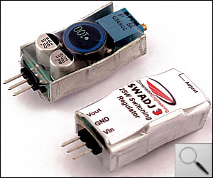 |
| SWADJ3 Voltage Converter |
I wired power pin 11 and ground pin 16 to the SWADJ3 input. Next I adjusted the SWADJ3 until it output 5V DC. Then I cut the AC/DC converter off the USB hub power cable and rewired the power cable to the SWADJ output so that the USB hub could now be powered directly from the iRobot Create battery.
 |
| Installed SWADJ3 |
Now I was able to unplug the three USB cables that were plugged into the laptop and replace them with a single USB connector to the hub. The three previous USB connected components: iRobot Create, PowerPod, and webcam were all plugged into the hub and receive power directly from the Create instead of the laptop.
 |
| 4-Port USB Hub |
 |
| Cleaned USB Cables |
I have been operating with these changes for the past three weeks and the results have been very positive. First off - I seem to have eliminated the PowerPod problems. Moving it to a dedicated power source really seems to have solved that issue. Not once have I experienced a loss of control over the PowerPod and I find myself using the neck even more now that I have confidence that it will work properly. In addition the changes seem to have resolved the problem that would cause the battery to slowly drain over the weekend. For two weekends straight the robot has stayed alive for the entire duration without my intervention. This was totally unexpected and a nice surprise for me.
But most importantly, I have GREATLY reduced both the USB/Serial interface connection problem and the docking power loss problem. Whereas before, I would experience these problems 2-3 a day now I only see them 2-3 times a week. These were the key problems that plagued me daily and rendered the robot nearly unusable. Unfortunately I have not completely eliminated those issues, so the robot is still not stable enough to be used in a completely autonomous manner, but the inconveniences now are infrequent enough that they don't really bother me much anymore. Having to ask a coworker to reboot my machine once a week is not a significant burden, so I am currently satisfied with the design and will probably not try to improve it anymore in these regards. If I were to attempt to improve its stability even more, I would probably try and reinsert the battery into the laptop. That would at least prevent the laptop from ever crashing due to brown-out. The cost however would be to significantly increase the weight and stress on the PowerPod and since I have new components planned for the head, I don't want to disturb that part of the design.
Here is the updated TPRobot software that I am using. It has the toggle controls for video and screen under the View menu. Currently I am turning off both video and screen during docking in order to minimize battery draw. In addition there is an alpha version of a shared whiteboard included that I have been developing so that I can easily make sketches on the robot screen. It is functional now but not finished, and I will cover it in more detail in a future post.
TPRobot_0.8.2.zip
Saturday, September 17, 2011
Robot upgrades
I reworked the robot power system a little bit and made some software changes to try and fix the problems that I have been having with it. I ran the robot remotely for three days this week to test the changes. Bad news first: I have not completely eliminated the glitches. I had a couple of power failures this week requiring a reboot. Good news: It seems that the robot is significantly more stable than before. Even though I had a couple problems I was able to predict them by monitoring the power system, so I think that I will be able to handle it in the future. As a bonus, I have significantly reduced or eliminated some other glitches that plagued the original system. The loss of the serial/USB connection only occurred once this week where before it would occur 2-3 times per day. Also I have not any problems with the PowerPod. I want to give it another full week of testing before I draw any conclusions, but if this stability persists I will post another part to the robot project detailing the changes that were made.
Friday, September 2, 2011
Sick Robot
My previous iRobot Create apparently did "burn out" its charging circuitry and was not able to charge its battery. I ordered a new Create, replaced the old one, and it fixed that problem. So my robot was back up for a few days but now I have a new problem! Very frequently the Create drops power to the serial pins when docking. When that happens the netbook goes - poof!, and instantly turns off. A major problem! So I am currently diagnosing the problem and trying to come up with a fix. My current plan is:
1. Determine if a lower power draw can help the problem. For example, turning off the screen or the video feed during docking.
2. Wire pin 9 instead of pin 12 which should should give me unregulated access to the battery and hopefully no power loss.
Those would be relatively easy fixes requiring no structural changes, but if I can't get either of those to work then I might have to resort to
3. Change the design and put the battery back into the netbook. That would require refashioning the "table" and putting a lot more weight up top. It would protect the netbook from any power drops. I don't really want to do this because I worry that it might cause problems with the PowerPod, but I may have no choice.
Monday, August 29, 2011
DIY Telepresence Robot - Part 8
Users Guide
This guide gives an overview of the control software, the robot behavior, Skype integration, and guidelines to keep the robot up and running. If handled correctly the robot is capable of autonomous operation for weeks at a time, but to keep the robot healthy it must be carefully monitored and used on a near daily basis. Left unattended over a weekend and the robot will likely die (refer to the Problems section for details)
Robot Controller
The TPRobot program is actually two applications in one. One instance runs on the Asus netbook and functions as the Create and PowerPod controller and listens for commands from the control computer, and another instance runs on the control computer and sends commands over the Internet to the first instance. These two aspects of the application or depicted visually as a tab control. The first tab is called "Local Connect" and embodies the robot interface. It has settings to interface the Create, the PowerPod, and to create a command listener.

The second tab - called the "Skype Connect" tab is used to configure the remote controller. All communication between the two applications is sent via the Skype network. Skype is primarily thought of as a VOIP app, but it is also a generic communication platform that can be leveraged to send messages between external applications. The Skype application serves as a proxy, setting up the connection and handling the data transmission. The bandwidth is not terribly high but for an application like this it is more than adequate. The benefit is that Skype handles all the messy details of connectivity, firewall traversal, encryption, and message reconstruction for you.

The driving controls are all keyboard based using a layout familiar to gamers.
IMPORTANT: The TPRobot window must maintain keyboard focus for the controls to operate properly. If you click on a different window while driving, the robot may continue moving even after you release the keys. Click back on the TPRobot window to regain control again.
The right hand controls the PowerPod. Each tap of the arrow keys or number pad will rotate the head a few degrees. In practice, head movement is not used very often. I usually just drive with the left and keep my hand on the mouse - only stopping to adjust the head if I bump into something or to talk to a person that is standing. Even then I typically only use the look up and look down controls because looking right and left is functionally the same as turning right and left.
The bottom half of the UI displays the robot speed and sensor status.
To customize the robot functionality, the robot controller can execute batch file scripts. Any batch files found in the \run\scripts folder will be made available under the "File->Run Scripts" menu. Scripts located on the robot controller can be executed by the control computer. Just about anything can be performed by the scripts, but the two useful examples provided in the release are RestartComputer.bat and RefreshWireless.bat the purpose of which should be obvious.
The robot has some major flaws. I have explored them a bit and - so far have not come up with permanent solutions. However, I have discovered ways to work around these problems and have come to terms with them. Once you learn to manage these issues the robot can be operated with very little outside help for weeks at at time. Still it is a good idea to have someone at the office that is well acquainted with the robot and its flaws to help you out when necessary.
Updated Solutions 10/11/2011-> Part 9: Upgraded Power Management
1. Charging
The biggest problems with the robot have to do with the battery draining. On a full charge the robot can operate for over an hour making short drives and video conferencing. That is ample time to talk to people and then get back to the charger. The problems start at the charger. When the iRobot Create docks with the charger it enters into its charge cycle and the battery light will start slowly blinking red. During this time the netbook is still on and drawing power, but the battery is still able to charge up. Once the battery becomes fully charged the Create will then show a solid green light and enter into a trickle charge state that is designed to keep the battery full. A flaw in the Create firmware prevents it from taking into account the current draw of the netbook however, and it never notices that the netbook is slowly draining the battery. It fails to reenter the charge state and it continues to show a green light for several hours while it drains away until - poof ! The battery and the netbook die.
There is no way to put the netbook into a low power "sleep" state because it must be ready at all times to accept control requests. The Asus motherboard does not support "wake on wireless LAN", so it cannot be put to sleep. The only way around the problem is to continually send a "reboot" command to the Create so that it will recheck the battery and restart the charge cycle. (Luckily there is an undocumented command 7 that handles this). So the TPRobot application must connect to the robot once every hour to send a reboot command and keep the battery charged. Great! - but that will only keep it alive for about 2 days straight. Even with this "hack" in place the Create somehow slowly loses track of the correct battery charge level, and the only way to recalibrate it is to take it off the charger and drive it around for a few seconds. After recalibration it can then be placed back on the charger and the process can start all over again. So at a minimum you MUST connect to the robot every one or two days and drive it around for a few moments - even on the weekends. Following this procedure I have been able to keep the robot operating continuously for a month. So that's not so bad -- except in conjunction with the next flaw.
2. Serial-USB Disconnect
This problem is more difficult to diagnose. Sometimes when the Create is getting back on the charger it momentarily drops its hardware connection to the netbook. This happens fairly frequently - maybe one out of every five times that it docks. As a result the TPRobot application loses all contact with the Create and is not able to reconnect to it without throwing an error. (Unauthorized Access Exception). Without the ability to communicate with the Create, the TPRobot is unable to send the reboot commands and so - again the robot battery will drain within a few hours. There are two ways to fix this. First - if a person physically unplugs and replugs the Create USB cable into the netbook, then the TPRobot application will be able to reestablish a connection. However if a person is not available then the only other way to fix it remotely is to reboot the netbook. So the second procedure the operator must follow is to notice whenever the TPRobot loses contact with the Create and send a Windows reboot command. This capability has been built into the software to simplify this task.
3. Docking power loss.
Similar to the above problem and a relatively new but serious problem. I only experienced it after 3 months of operation after replacing my Create robot with a new one. Sometimes during docking (presumably on the transition between non-charging and charging) the Create will drop all power to the netbook and the netbook will instantly turn off. I have yet to understand this problem but it does not bode well for the overall design. It may have been a mistake to remove the battery from the netbook - at least with the battery, these brown outs would not be catastrophic.
4. PowerPod Craziness
Another difficult problem. Once every week or two I will lose complete control of the PowerPod when attempting to rotate it. I don't know if it's a transient power issue or software bugs in the drivers, but whatever happens is catastrophic. The PowerPod will just suddenly rotate to maximum on both axis (look up at ceiling) and the motors will stay engaged trying to rotate even further. Attempting to rotate it back has inconsistent results. Often it will just move all to way in another direction. The only way to fix it seems to be to "detach" the TPRobot interface, unplug the USB cable on the back of the PowerPod, and physically force it back into home position. Then reconnect the USB and try to gain control again. This may have to be done one or more times before the hardware and drivers finally synchronize. I don't really have not investigated this problem very much so I cannot really say whether it is a fault with the hardware integration, the Eagletron driver software, or the TPRobot software.
Next-> Part 9: Upgraded Power Management
This guide gives an overview of the control software, the robot behavior, Skype integration, and guidelines to keep the robot up and running. If handled correctly the robot is capable of autonomous operation for weeks at a time, but to keep the robot healthy it must be carefully monitored and used on a near daily basis. Left unattended over a weekend and the robot will likely die (refer to the Problems section for details)
Robot Controller
The TPRobot program is actually two applications in one. One instance runs on the Asus netbook and functions as the Create and PowerPod controller and listens for commands from the control computer, and another instance runs on the control computer and sends commands over the Internet to the first instance. These two aspects of the application or depicted visually as a tab control. The first tab is called "Local Connect" and embodies the robot interface. It has settings to interface the Create, the PowerPod, and to create a command listener.
- iRobot Serial Port - The COM port number for interfacing with the iRobot Create
- Tracker Pod - Enables attachment and control of the Eagletron PowerPod.
- Allow Network Control - Enables a network command listener. Connections and commands are sent through the Skype network.
- Password - Skype authenticates which accounts are able to connect and issued commands to TPRobot and all Skype traffic is encrypted. However, for additional security this password is also used to authenticate the connecting peer.
- Attach - Attempts to connect to the Create and PowerPod. Once connected the robot will be in "drive" mode and the battery will not be charging - even when it is sitting on the charger.
- Detach - Disconnects from the Create and PowerPod and puts the Create into charging mode. You must detach the robot to charge the battery.
The second tab - called the "Skype Connect" tab is used to configure the remote controller. All communication between the two applications is sent via the Skype network. Skype is primarily thought of as a VOIP app, but it is also a generic communication platform that can be leveraged to send messages between external applications. The Skype application serves as a proxy, setting up the connection and handling the data transmission. The bandwidth is not terribly high but for an application like this it is more than adequate. The benefit is that Skype handles all the messy details of connectivity, firewall traversal, encryption, and message reconstruction for you.
- Skype ID - The Skype ID of the account being used on the netbook. Separate accounts and ID's should be used for the netbook and control computer.
- Password - This should match the password configured on the netbook.
- Connect - Creates an authenticated Skype connection to the robot controller. Upon successful connection the screen will be turned on and the robot will be automatically "attached" and drive mode initiated.
- Disconnect - Closes the connection to the robot controller. The robot interface is "detached" and the charge mode is initiated. To reduce the power draw on the battery while in charge mode the robot screen is also turned off.
The driving controls are all keyboard based using a layout familiar to gamers.
- Move Forward - W
- Move Backward - S
- Turn Left - A
- Turn Right - D
- Up-Shift - Space
- Look Up - Up Arrow OR NumPad 5
- Look Down - Down Arrow OR NumPad 8
- Look Left - Left Arrow OR NumPad 4
- Look Right - Right Arrow OR NumPad 6
- Look Straight - NumPad 7
IMPORTANT: The TPRobot window must maintain keyboard focus for the controls to operate properly. If you click on a different window while driving, the robot may continue moving even after you release the keys. Click back on the TPRobot window to regain control again.
The right hand controls the PowerPod. Each tap of the arrow keys or number pad will rotate the head a few degrees. In practice, head movement is not used very often. I usually just drive with the left and keep my hand on the mouse - only stopping to adjust the head if I bump into something or to talk to a person that is standing. Even then I typically only use the look up and look down controls because looking right and left is functionally the same as turning right and left.
The bottom half of the UI displays the robot speed and sensor status.
- Speed - The text displays the independent speed of each wheel, while the progress indicator shows the total forward or backward speed of the robot. The digit to the right of the progress indicator shows the current gear.
- Dock - Turns orange when the robot is within proximity (about 8 feet) and facing towards the charging base. Turns green when the robot has successfully docked and has electrical contact with the charging base.
- Auto Dock - The button becomes enabled when the charger base proximity light is on. Clicking it initiates the auto-dock function - during which time all drive controls are disabled and the robot will automatically enter a search pattern and attempt to dock with the charge base and start the charging cycle. The auto dock feature is very imprecise and will often take 2 or 3 attempts before correctly docking. It is best to line up the robot manually before selecting Auto Dock.
- Bump - Turns red when the robot hits an obstacle and the front bumper is activated. The robot will immediately stop all forward momentum when a bump is detected. There are no bump sensors for the rear or sides of the robot.
- Error - Turns red if a software exception occurs on the robot controller.
- Battery - Displays battery capacity and usage data. The text indicates the actual voltage and current draw detected on the battery. The progress indicator gives an "estimate" of the amount of battery capacity left. The progress indicator is not always accurate - especially when the robot is sitting on the charger. After a few minutes of usage the progress indicator becomes more accurately calibrated.
To customize the robot functionality, the robot controller can execute batch file scripts. Any batch files found in the \run\scripts folder will be made available under the "File->Run Scripts" menu. Scripts located on the robot controller can be executed by the control computer. Just about anything can be performed by the scripts, but the two useful examples provided in the release are RestartComputer.bat and RefreshWireless.bat the purpose of which should be obvious.
The robot has some major flaws. I have explored them a bit and - so far have not come up with permanent solutions. However, I have discovered ways to work around these problems and have come to terms with them. Once you learn to manage these issues the robot can be operated with very little outside help for weeks at at time. Still it is a good idea to have someone at the office that is well acquainted with the robot and its flaws to help you out when necessary.
Updated Solutions 10/11/2011-> Part 9: Upgraded Power Management
1. Charging
The biggest problems with the robot have to do with the battery draining. On a full charge the robot can operate for over an hour making short drives and video conferencing. That is ample time to talk to people and then get back to the charger. The problems start at the charger. When the iRobot Create docks with the charger it enters into its charge cycle and the battery light will start slowly blinking red. During this time the netbook is still on and drawing power, but the battery is still able to charge up. Once the battery becomes fully charged the Create will then show a solid green light and enter into a trickle charge state that is designed to keep the battery full. A flaw in the Create firmware prevents it from taking into account the current draw of the netbook however, and it never notices that the netbook is slowly draining the battery. It fails to reenter the charge state and it continues to show a green light for several hours while it drains away until - poof ! The battery and the netbook die.
There is no way to put the netbook into a low power "sleep" state because it must be ready at all times to accept control requests. The Asus motherboard does not support "wake on wireless LAN", so it cannot be put to sleep. The only way around the problem is to continually send a "reboot" command to the Create so that it will recheck the battery and restart the charge cycle. (Luckily there is an undocumented command 7 that handles this). So the TPRobot application must connect to the robot once every hour to send a reboot command and keep the battery charged. Great! - but that will only keep it alive for about 2 days straight. Even with this "hack" in place the Create somehow slowly loses track of the correct battery charge level, and the only way to recalibrate it is to take it off the charger and drive it around for a few seconds. After recalibration it can then be placed back on the charger and the process can start all over again. So at a minimum you MUST connect to the robot every one or two days and drive it around for a few moments - even on the weekends. Following this procedure I have been able to keep the robot operating continuously for a month. So that's not so bad -- except in conjunction with the next flaw.
2. Serial-USB Disconnect
This problem is more difficult to diagnose. Sometimes when the Create is getting back on the charger it momentarily drops its hardware connection to the netbook. This happens fairly frequently - maybe one out of every five times that it docks. As a result the TPRobot application loses all contact with the Create and is not able to reconnect to it without throwing an error. (Unauthorized Access Exception). Without the ability to communicate with the Create, the TPRobot is unable to send the reboot commands and so - again the robot battery will drain within a few hours. There are two ways to fix this. First - if a person physically unplugs and replugs the Create USB cable into the netbook, then the TPRobot application will be able to reestablish a connection. However if a person is not available then the only other way to fix it remotely is to reboot the netbook. So the second procedure the operator must follow is to notice whenever the TPRobot loses contact with the Create and send a Windows reboot command. This capability has been built into the software to simplify this task.
3. Docking power loss.
Similar to the above problem and a relatively new but serious problem. I only experienced it after 3 months of operation after replacing my Create robot with a new one. Sometimes during docking (presumably on the transition between non-charging and charging) the Create will drop all power to the netbook and the netbook will instantly turn off. I have yet to understand this problem but it does not bode well for the overall design. It may have been a mistake to remove the battery from the netbook - at least with the battery, these brown outs would not be catastrophic.
4. PowerPod Craziness
Another difficult problem. Once every week or two I will lose complete control of the PowerPod when attempting to rotate it. I don't know if it's a transient power issue or software bugs in the drivers, but whatever happens is catastrophic. The PowerPod will just suddenly rotate to maximum on both axis (look up at ceiling) and the motors will stay engaged trying to rotate even further. Attempting to rotate it back has inconsistent results. Often it will just move all to way in another direction. The only way to fix it seems to be to "detach" the TPRobot interface, unplug the USB cable on the back of the PowerPod, and physically force it back into home position. Then reconnect the USB and try to gain control again. This may have to be done one or more times before the hardware and drivers finally synchronize. I don't really have not investigated this problem very much so I cannot really say whether it is a fault with the hardware integration, the Eagletron driver software, or the TPRobot software.
Next-> Part 9: Upgraded Power Management
Thursday, August 25, 2011
DIY Telepresence Robot - Part 7
Software Install
Designing and creating the hardware was a relatively straight forward task. I had a few false starts and design changes, but since I used high level parts the construction came together rather quickly. The software however is a much longer and on-going project - not because it is particularly difficult but simply because that is the nature of software development. Software takes a long time to mature properly, and between work and home-life I only have a few hours a week to work on side projects like this. I considered selling the software since it represents a good chunk of investigation, time, and expertise on my part. However with selling a product comes the moral obligation of quality assurance and ongoing support - neither of which I am willing to commit to. Plus - I have taken my fair share of open-source and sample code from the Net over the years, and I figure it's about time that I pay back that debt, so I am releasing all of the source code and binaries for free under the "whatever the hell you want to do with it" license.
Before installing the control software you have to set up the OS and support software. Here is a guide for configuring the netbook (as best as I can remember). If something is missing contact me and I can update this procedure.
1. Set Auto-login
Configure your login account so that it will automatically log in on startup because you will probably need to remotely reboot the computer fairly often. (Be aware of any company security policies that this may affect)
2. Disable automatic power management
You don't want your computer going to sleep on you, so go into your power options and set the computer to never dim the screen, never turn off the screen, and never sleep when plugged in. It's a good idea to reduce the brightness of your screen a bit to draw less power and increase your battery life. Disable any screen savers.
3. Disable unnecessary applications.
To conserve power you don't want a bunch of background apps burning CPU cycles. I can't be specific here but go through your Services, installed applications, and startup apps and remove as much clutter as you can. For example - virus scanners, auto-updating software, file indexers, quick start services, tray tools, etc.. are all useless since this machine is dedicated to a single app.
4. Install some type of VNC or Remote Desktop software.
At some point you will absolutely need to log in to your desktop and diagnose or configure your environment. Having remote desktop software is a life saver instead of asking a coworker to come and handle it.
5. Install the web cam.
Just install the basic drivers and avoid any extra applications that come with it.
6. Install Skype.
One crucial feature that was removed in recent versions of Skype (5+) is the "auto-answer with full-screen video" feature. This is really important since you want your robot to automatically answer your video call when you Skype it and display your face in full screen without any human intervention. For this reason you should install a legacy version of Skype that still has this all-important feature. I am using Skype 4.2.0.187 and that works well for me and is compatible with a Skype 5 peer call.
Setup a new Skype account for the robot and configure Skype to auto-launch and auto-login at startup. Also configure Skype to use the LifeCam video and microphone and set it to auto-answer with full screen video. Another issue is that Skype attempts to automatically adjust the microphone level when it detects silence. When having a conversation with someone this is fine, but while driving around in silence it tends to amplify all the robot motor noises and bumps to an annoying level. It is a good idea to configure Skype with a fixed mic level to minimize this noise.
7. Install Eagletron PowerPod Service.
The software interface to the PowerPod is in the form of an ActiveX control that communicates indirectly with the hardware via a Service application. The "Eagletron TrackerPod Service" should be installed to startup automatically. You can install it indirectly through their tester utility, or you can get it directly here.
TrackerCam_setup_SERVICE_5.3.1.29.zip
8. Install the TPRobot application on the netbook.
This application serves both as the direct robot interface and also the remote control app. It was based originally on Johnny Lee's C# robot driver and still has the same basic GUI design and a few snippets of code left from that project, however the bulk of the code has been completely rewritten (still in C#). The TPRobot application should be added to the Startup folder so that it automatically launches on startup. The source and binaries are here. There is no installer so just unzip the contents to a location of your choice.
TPRobot_0.6.2.zip
9. Register the Skype interface
From the command line type "regsvr32 Skype4COM.dll"
10. Run the application.
Execute \run\TPRobot.exe
11. Install TPRobot on the control computer.
Repeat steps 6 and 8-10 on a your control computer at home. You should create a personal Skype account instead of reusing the robot account.
The next post will be devoted to how to use the software and the robot.
Disclaimer: While this code has settled down significantly over the last couple of months to a relatively stable and usable level - this is still very much prototype/alpha level code and there is much room for improvement. Most of the problems now are just annoyances, but there are still a couple of major problems that you must be constantly aware of. I will detail all of this in the next post.
Next-> Part 8: Software Usage
Monday, August 22, 2011
robot troubles
Finally had my first major break-down of the telepresence robot after 3 months of operation. A week and a half ago I tried to connect on Monday morning and found that the computer was down. Not an entirely unusual occurrence - I have had occasional battery drains over the weekend if I fail to monitor the robot. However the usual attempts at battery recharge failed. Assuming the battery had somehow gone bad, I purchased a new battery, charged it up, got the robot working again one night and then the next morning - same thing - battery drained. After a number of unsuccessful attempts to charge the batteries I have given up and decided that the on-board charger has broken. I don't have the patience to deal with the back-and-forth with tech support to try and get this thing resolved. I am really spoiled and I miss my virtual presence at the office, so I went ahead and ordered a new Create and hopefully that will fix the problem. I hope this is not a frequent occurrence.
DIY Telepresence Robot - Part 6
Final Assembly
Once all the parts have been created, we just need to put everything together to finish the robot. When we built the body frame in part 4 we did not permanently attach the vertical shaft to the H-foot in order to allow for cables. It is now time to run those cables. Carefully drill and smooth an oval shaped hole in the back of the support shaft about 8 inches from the top. It is best to drill several adjacent holes using small drill bits, and then use increasingly larger bits until the holes merge into a single oval. The oval should be large enough to comfortably pass a Type-A USB connector through. This will be the where the cables exit the shaft on their way to the netbook.
Push the USB end of the Create USB to Robot Cable through the hole in the bottom of the H-foot and snake the cable up through the bottom of the shaft and out through the oval hole. Now feed the newly created netbook power cord (up or down) through the vertical shaft and H-foot as well. With both cables in place now we can connect the body frame. Tap the vertical shaft all the way onto the H-foot being careful not to damage or bend any part of the frame. It may be helpful to sand down the H-foot connector a little to ease this process.
Before attaching the body frame, turn the iRobot Create over and use the supplied wheel clamps to fasten the wheels in the retracted position. Now turn it back over and use the 1 1/4" long 6-32 mounting screws to attach the finished body frame to the iRobot Create.

Plug the DB-25 connector and the round Mini-DIN serial cable into the Create. Neatly secure all the extra cabling and the AnyVolt3 in the Create cargo bay area using some electrical tape and/or twist ties. The picture below shows what my cargo bay looks like. (The gray coiled cable is just some extra unattached wire that I included for future use. I also added some DC plug connectors to the AnyVolt3 to make it easier to disconnect the electrical system.)
Screw the Eagletron and notebook platform onto the bolt at the top of the shaft. Then press the netbook onto the platform and make sure it is centered and securely fastened with the velcro. Insert the power plug and the iRobot serial to USB cable to the netbook. Attach a USB cable from the back of the Eagletron to the netbook.
Place the webcam on the top of the open netbook screen and fasten it with tape or velcro. Plug the webcam's USB cable into the netbook. The USB cables will bow out to the sides of the robot and may occasionally brush against walls and doors. USB right angle adapters can be used to reduce the width of these cables. Once everything is attached, use some wire management clips and ingenuity to secure the extra cabling. The picture below shows what I managed to come up with, but I really didn't try that hard and I am sure others could vastly improve the appearance of their robot.
The last thing that needs to be done is to create of a docking station. You should clear a small 4x4 area of all obstructions and floor clutter. Secure the iRobot home base charger on the floor with some tape so the robot will not push it out of position. Plug the charger base in and make sure the power cords are well out of the approach pathway. To assist docking I fastened a cheap mirror behind the charge base so that I can better see the robot in relation to the wall and charger on approach.
The robot is complete. Now we just need to install and configure the software.
Next--> Part 7: Software Install
Once all the parts have been created, we just need to put everything together to finish the robot. When we built the body frame in part 4 we did not permanently attach the vertical shaft to the H-foot in order to allow for cables. It is now time to run those cables. Carefully drill and smooth an oval shaped hole in the back of the support shaft about 8 inches from the top. It is best to drill several adjacent holes using small drill bits, and then use increasingly larger bits until the holes merge into a single oval. The oval should be large enough to comfortably pass a Type-A USB connector through. This will be the where the cables exit the shaft on their way to the netbook.
Push the USB end of the Create USB to Robot Cable through the hole in the bottom of the H-foot and snake the cable up through the bottom of the shaft and out through the oval hole. Now feed the newly created netbook power cord (up or down) through the vertical shaft and H-foot as well. With both cables in place now we can connect the body frame. Tap the vertical shaft all the way onto the H-foot being careful not to damage or bend any part of the frame. It may be helpful to sand down the H-foot connector a little to ease this process.
Before attaching the body frame, turn the iRobot Create over and use the supplied wheel clamps to fasten the wheels in the retracted position. Now turn it back over and use the 1 1/4" long 6-32 mounting screws to attach the finished body frame to the iRobot Create.
Plug the DB-25 connector and the round Mini-DIN serial cable into the Create. Neatly secure all the extra cabling and the AnyVolt3 in the Create cargo bay area using some electrical tape and/or twist ties. The picture below shows what my cargo bay looks like. (The gray coiled cable is just some extra unattached wire that I included for future use. I also added some DC plug connectors to the AnyVolt3 to make it easier to disconnect the electrical system.)
 |
| Cargo Bay |
Screw the Eagletron and notebook platform onto the bolt at the top of the shaft. Then press the netbook onto the platform and make sure it is centered and securely fastened with the velcro. Insert the power plug and the iRobot serial to USB cable to the netbook. Attach a USB cable from the back of the Eagletron to the netbook.
Place the webcam on the top of the open netbook screen and fasten it with tape or velcro. Plug the webcam's USB cable into the netbook. The USB cables will bow out to the sides of the robot and may occasionally brush against walls and doors. USB right angle adapters can be used to reduce the width of these cables. Once everything is attached, use some wire management clips and ingenuity to secure the extra cabling. The picture below shows what I managed to come up with, but I really didn't try that hard and I am sure others could vastly improve the appearance of their robot.
 |
| Rear cables |
The last thing that needs to be done is to create of a docking station. You should clear a small 4x4 area of all obstructions and floor clutter. Secure the iRobot home base charger on the floor with some tape so the robot will not push it out of position. Plug the charger base in and make sure the power cords are well out of the approach pathway. To assist docking I fastened a cheap mirror behind the charge base so that I can better see the robot in relation to the wall and charger on approach.
 |
| Docking Station |
The robot is complete. Now we just need to install and configure the software.
Next--> Part 7: Software Install
Saturday, August 13, 2011
DIY Telepresence Robot - Part 5
The Electrical System
Powering the netbook is one of the more interesting design problems. Johnny Lee came up with a novel solution. He modified the charger base to output 110V AC instead of DC. Then he piled both AC/DC converter bricks onto the iRobot and charged it and the netbook using AC power supplied by the charger. The advantage to this approach is simplicity. By keeping both electrical systems intact and separate, he avoided the design problems associated with unifying them. But keeping both power systems on the robot adds weight to the unit - creating docking problems. More importantly, the conversion of the charger base to AC and the exposure of high-voltage contacts creates a potential fire hazard which renders the design inappropriate for a place of business.
Initially I tried to keep the dual electrical system but address its problems by designing a custom plug and socket mechanism. The socket would capture and engage the plug during auto-docking to charge the netbook, but the iRobot docking motion proved to be too erratic for a physical solution. No plug mechanism had enough positional tolerance. So instead I abandoned dual electrical systems and decided to unify the systems and power the netbook directly from the iRobot battery.
Luckily the iRobot Create already has an electrical pathway to its battery through its serial interface so no physical modifications have to be made to the iRobot. The only remaining problem then is to convert the battery feed to the proper voltage and current for the netbook. The power requirements for the Asus 1015PE are 19 Volts and 2.1 Watts as listed on the AC/DC converter brick. To meet this non-standard voltage, I found a nifty little product called the AnyVolt3. It can take any input voltage from 5 to 30V and step it up or down to any output voltage between 3 and 24Vwith reasonable efficiency. The output voltage is adjusted by a little potentiometer dial on the unit. Our iRobot battery supplies a voltage ranging from about 12V to 16V depending on its charge level, so we just need to boost the power by 3 or 4V for the Asus netbook. If you choose a different netbook, then the AnyVolt3 should easily be able to accommodate its different voltage requirement.
The Asus claims to draw up to 2.1 Amps of power. I hooked up a multimeter to test this but never saw that much current draw from the netbook during normal usage even with all the robot components connected and operating. I assume that a 2.1A draw could occur during charging, but that's not possible without a battery attached. So the netbook does a pretty good job of power management and the normal power draw sits somewhere around 0.5A with occasional spikes only going as high as 1.2A under load conditions. Looking at the iRobot Create serial interface we see that pins 10, 11, and 12 each supply the battery voltage at 1.5 Amps a piece, so in theory I could get all the power I needed from a single pin. However the AnyVolt3 draws more current than it outputs when up-converting voltage. In other words, if the netbook is drawing 1.2A, then the AnyVolt3 will be drawing MORE than 1.2A in order to generate 19V. To be on the safe side I used two pins in parallel to provide up to 3A to satisfy the full currency requirement.
Hooking all this up is incredibly simple. Plug a male DB-25 serial connector into the iRobot. Now cut two short lengths (about 10") of power wire and connect one of them to pin 10 and the other one to pin 12. If you use a serial breakout board connector then you can simply screw the wires in and avoid soldering. The other ends of both power wires will overlap and screw in to the positive input terminal of the AnyVolt3. Now cut a short length of ground wire and string it between pin 14 (GND) of the serial connector and the negative input terminal of the AnyVolt3.
Next configure the AnyVolt3 output voltage. Power on the iRobot and use a voltage meter to test the output terminal of the AnyVolt3. Turn the AnyVolt's potentiometer until you detect a 19V output voltage. To finish the wiring first cut the DC end of the netbook power cord just above the AC/DC converter brick. Attach the cut ends of the wire to the positive and negative output terminals of the AnyVolt3. Finally plug the power plug into the netbook.
In summary, the iRobot serial interface should be connected by three wires (2 positive, 1 ground) to the AnyVolt3 input and the netbook should be connected to the AnyVolt3 output through its power cord. You should now be able to boot up and test the netbook without a battery using only the power supplied by the iRobot. The electrical system is now complete. Fully charged, the robot and netbook can operate between 1 and 1 1/2 hours assuming that it only travels short distances and mainly sits still during conversations. That is long enough for most daily activities including short visits to multiple coworker offices and even medium length formal meetings in a conference room.
There is one major problem with this design. When the iRobot gets back on the charger, it enters a charging cycle where it draws a large amount of current to charge the battery with. In order to remain responsive the netbook must stay powered and awake at all times - even on the charger, so the netbook is drawing a bit of current during the charge cycle as well. We can minimize the impact by doing things in software like turning off the screen, but we cannot eliminate it, so we are left with a minimum draw of about 250mA just to keep the netbook alive. You would expect that the iRobot charger would compensate for the netbook draw and be able to keep the battery fully charged, but there is a flaw in the iRobot design.
Once the iRobot detects that it has fully charged the battery, it enters into a trickle-charge mode that is designed to keep the battery at full charge. Unfortunately during this mode the iRobot never bothers to test whether the battery is staying charged or has a draw on it. It just assumes that the trickle is enough, but our netbook draw far exceeds the trickle charge, and so the battery will eventually drain even if the robot is sitting on the charger and the green "full charge" light is on. Once the battery drains, it is difficult to get the robot "unconfused" about its charge state and operating properly. I have implemented some software tricks to "mostly" overcome this problem but I have not been able to fully solve it, and so battery health is a constant and nagging issue with this robot. I will go into some more detail about this when I cover the software in a future post.
With the electrical system complete we have manufactured all of the robot parts, so we just need to put all the pieces together the complete the robot assembly. The next post will cover the final assembly.
Next--> Part 6: Final Assembly
Powering the netbook is one of the more interesting design problems. Johnny Lee came up with a novel solution. He modified the charger base to output 110V AC instead of DC. Then he piled both AC/DC converter bricks onto the iRobot and charged it and the netbook using AC power supplied by the charger. The advantage to this approach is simplicity. By keeping both electrical systems intact and separate, he avoided the design problems associated with unifying them. But keeping both power systems on the robot adds weight to the unit - creating docking problems. More importantly, the conversion of the charger base to AC and the exposure of high-voltage contacts creates a potential fire hazard which renders the design inappropriate for a place of business.
Initially I tried to keep the dual electrical system but address its problems by designing a custom plug and socket mechanism. The socket would capture and engage the plug during auto-docking to charge the netbook, but the iRobot docking motion proved to be too erratic for a physical solution. No plug mechanism had enough positional tolerance. So instead I abandoned dual electrical systems and decided to unify the systems and power the netbook directly from the iRobot battery.
Luckily the iRobot Create already has an electrical pathway to its battery through its serial interface so no physical modifications have to be made to the iRobot. The only remaining problem then is to convert the battery feed to the proper voltage and current for the netbook. The power requirements for the Asus 1015PE are 19 Volts and 2.1 Watts as listed on the AC/DC converter brick. To meet this non-standard voltage, I found a nifty little product called the AnyVolt3. It can take any input voltage from 5 to 30V and step it up or down to any output voltage between 3 and 24Vwith reasonable efficiency. The output voltage is adjusted by a little potentiometer dial on the unit. Our iRobot battery supplies a voltage ranging from about 12V to 16V depending on its charge level, so we just need to boost the power by 3 or 4V for the Asus netbook. If you choose a different netbook, then the AnyVolt3 should easily be able to accommodate its different voltage requirement.
 |
| AnyVolt3 |
The Asus claims to draw up to 2.1 Amps of power. I hooked up a multimeter to test this but never saw that much current draw from the netbook during normal usage even with all the robot components connected and operating. I assume that a 2.1A draw could occur during charging, but that's not possible without a battery attached. So the netbook does a pretty good job of power management and the normal power draw sits somewhere around 0.5A with occasional spikes only going as high as 1.2A under load conditions. Looking at the iRobot Create serial interface we see that pins 10, 11, and 12 each supply the battery voltage at 1.5 Amps a piece, so in theory I could get all the power I needed from a single pin. However the AnyVolt3 draws more current than it outputs when up-converting voltage. In other words, if the netbook is drawing 1.2A, then the AnyVolt3 will be drawing MORE than 1.2A in order to generate 19V. To be on the safe side I used two pins in parallel to provide up to 3A to satisfy the full currency requirement.
Hooking all this up is incredibly simple. Plug a male DB-25 serial connector into the iRobot. Now cut two short lengths (about 10") of power wire and connect one of them to pin 10 and the other one to pin 12. If you use a serial breakout board connector then you can simply screw the wires in and avoid soldering. The other ends of both power wires will overlap and screw in to the positive input terminal of the AnyVolt3. Now cut a short length of ground wire and string it between pin 14 (GND) of the serial connector and the negative input terminal of the AnyVolt3.
Next configure the AnyVolt3 output voltage. Power on the iRobot and use a voltage meter to test the output terminal of the AnyVolt3. Turn the AnyVolt's potentiometer until you detect a 19V output voltage. To finish the wiring first cut the DC end of the netbook power cord just above the AC/DC converter brick. Attach the cut ends of the wire to the positive and negative output terminals of the AnyVolt3. Finally plug the power plug into the netbook.
 |
| Electrical Wiring |
In summary, the iRobot serial interface should be connected by three wires (2 positive, 1 ground) to the AnyVolt3 input and the netbook should be connected to the AnyVolt3 output through its power cord. You should now be able to boot up and test the netbook without a battery using only the power supplied by the iRobot. The electrical system is now complete. Fully charged, the robot and netbook can operate between 1 and 1 1/2 hours assuming that it only travels short distances and mainly sits still during conversations. That is long enough for most daily activities including short visits to multiple coworker offices and even medium length formal meetings in a conference room.
There is one major problem with this design. When the iRobot gets back on the charger, it enters a charging cycle where it draws a large amount of current to charge the battery with. In order to remain responsive the netbook must stay powered and awake at all times - even on the charger, so the netbook is drawing a bit of current during the charge cycle as well. We can minimize the impact by doing things in software like turning off the screen, but we cannot eliminate it, so we are left with a minimum draw of about 250mA just to keep the netbook alive. You would expect that the iRobot charger would compensate for the netbook draw and be able to keep the battery fully charged, but there is a flaw in the iRobot design.
Once the iRobot detects that it has fully charged the battery, it enters into a trickle-charge mode that is designed to keep the battery at full charge. Unfortunately during this mode the iRobot never bothers to test whether the battery is staying charged or has a draw on it. It just assumes that the trickle is enough, but our netbook draw far exceeds the trickle charge, and so the battery will eventually drain even if the robot is sitting on the charger and the green "full charge" light is on. Once the battery drains, it is difficult to get the robot "unconfused" about its charge state and operating properly. I have implemented some software tricks to "mostly" overcome this problem but I have not been able to fully solve it, and so battery health is a constant and nagging issue with this robot. I will go into some more detail about this when I cover the software in a future post.
With the electrical system complete we have manufactured all of the robot parts, so we just need to put all the pieces together the complete the robot assembly. The next post will cover the final assembly.
Next--> Part 6: Final Assembly
Subscribe to:
Posts (Atom)